

1 HP = 4 CFM at 100 psi
1 to 50 HP typically Reciprocating units
100 and above typically Rotary Screw or Centrifugal
‘Oil Free’ means no lubricating oil contacts the compressed air
1 HP electric input = 0.912 kW/HP Input (with efficiencies)
1 HP Gas unit = 9,000 to 11,000 BTUs/HP Input
First Costs, Maintenance and Paybacks
Types of Air Compressors
There are three basic types of air compressors:
- Reciprocating (Recip)
- Rotary Screw (Screw)
- Rotary Centrifugal (Centrifugal)
These types are further defined by:
- the number of compression stages
- method of cooling (air, water, oil)
- drive method (motor, engine, steam, other)
- how they are lubricated (oil, oil-free)
- packaged or custom-built
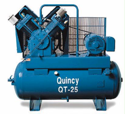
Reciprocating Units
Reciprocating air compressors are positive displacement compressors. This means they are taking in successive volumes of air which is confined within a closed space and elevating this air to a higher pressure. The reciprocating air compressor accomplishes this by using a piston within a cylinder as the compressing and displacing element.
The reciprocating air compressor is considered single acting when the compressing is accomplished using only one side of the piston. A compressor using both sides of the piston is considered double acting.
The reciprocating air compressor uses a number of automatic spring loaded valves in each cylinder that open only when the proper differential pressure exists across the valve.
Inlet valves open when the pressure in the cylinder is slightly below the intake pressure. Discharge valves open when the pressure in the cylinder is slightly above the discharge pressure.
A compressor is considered to be single stage when the entire compression is accomplished with a single cylinder or a group of cylinders in parallel. Many applications involve conditions beyond the practical capability of a single compression stage. Too great a compression ration (absolute discharge pressure/absolute intake pressure) may cause excessive discharge temperature or other design problems.
For practical purposes most plant air reciprocating air compressors over 100 horsepower are built as multi-stage units in which two or more steps of compression are grouped in series. The air is normally cooled between the stages to reduce the temperature and volume entering the following stage.
Reciprocating air compressors are available either as air-cooled or water-cooled in lubricated and non-lubricated configurations, may be packaged, and provide a wide range of pressure and capacity selections.
Rotary Screw Compressors
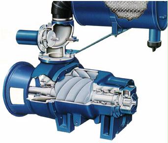 Rotary air compressors are positive displacement compressors. The most common rotary air compressor is the single stage helical or spiral lobe oil flooded screw air compressor. These compressors consist of two rotors within a casing where the rotors compress the air internally. There are no valves. These units are basically oil cooled (with air cooled or water cooled oil coolers) where the oil seals the internal clearances.
Since the cooling takes place right inside the compressor, the working parts never experience extreme operating temperatures. The rotary compressor, therefore, is a continuous duty, air cooled or water cooled compressor package.
Because of the simple design and few wearing parts, rotary screw air compressors are easy to maintain, operate and provide great installation flexibility. Rotary air compressors can be installed on any surface that will support the static weight.
The two stage oil flooded rotary screw air compressor uses pairs of rotors in a combined air end assembly. Compression is shared between the first and second stages flowing in series. This increases the overall compression efficiency up to fifteen percent of the total full load kilowatt consumption. The two stage rotary air compressor combines the simplicity and flexibility of a rotary screw compressor with the energy efficiency of a two stage double acting reciprocating air compressor. Two stage rotary screw air compressors are available air cooled and water cooled and fully packages.
The oil free rotary screw air compressor utilizes specially designed air ends to compress air without oil in the compression chamber yielding true oil free air. Oil free rotary screw air compressors are available air cooled and water cooled and provide the same flexibility as oil flooded rotaries when oil free air is required.
Rotary screw air compressors are available air cooled and water cooled, oil flooded and oil free, single stage and two stage. There is a wide range of availability in configuration and in pressure and capacity.
Centrifugal Compressors
The centrifugal air compressor is a dynamic compressor which depends on transfer of energy from a rotating impeller to the air. The rotor accomplishes this by changing the momentum and pressure of the air. This momentum is converted to useful pressure by slowing the air down in a stationary diffuser.
The centrifugal air compressor is an oil free compressor by design. The oil lubricated running gear is separated from the air by shaft seals and atmospheric vents.
The centrifugal is a continuous duty compressor, with few moving parts, that is particularly suited to high volume applications, especially where oil free air is required.
Centrifugal air compressors are water cooled and may be packaged; typically the package includes the after-cooler and all controls.
Air Systems
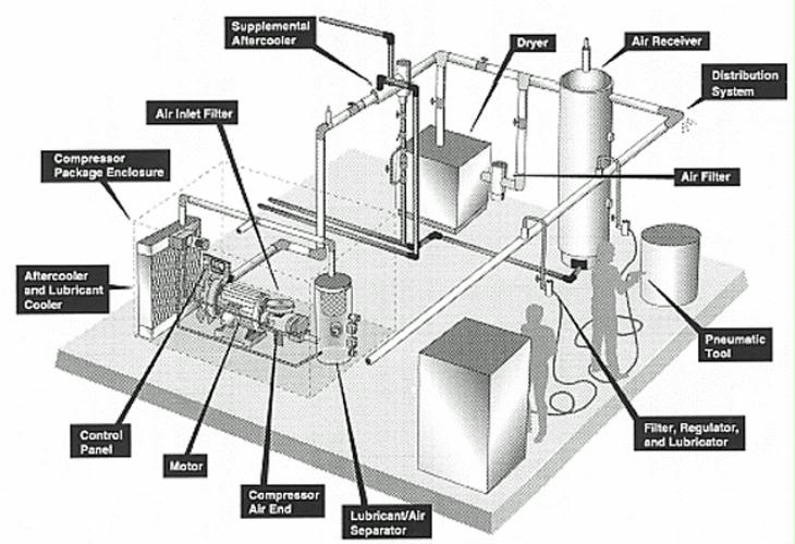
In addition to the air compressor package that includes the drive, air end, and cooling system, complete air systems include:
- Receiver Tanks
- Air Dryers
- Filters
- Piping Distribution Systems
Receiver Tanks
The air receivers:
- provide storage capacity to prevent rapid compressor cycling
- reduce wear and tear on compression module, inlet control system, and motor
- eliminate pulsing air flow
- avoid overloading purification system with surges in air demand
- damp out the dew point and temperature spikes that follow regeneration
A rule of thumb is to provide a minimum of one gallon of receiver capacity for each cubic foot of compressor flow.
Air Dryers
Moisture, either liquid or vapor, is present in compressed air as it exits the compressor system. If this moisture is not properly removed, your compressed air system can lose efficiency and require dramatically increased maintenance, which can result in costly downtime.
The majority of pneumatic instruments and processes can not tolerate hot compressed air, compressors are normally supplied with after-coolers and moisture separators. After-coolers are heat exchangers that utilize either water or ambient air to cool the compressed air. As the water and lubricant vapors within the compressed air cool, a significant amount condenses into liquid. An after-cooler discharging compressed air at 100F passes 67 gallons of water per 1,000 scfm per 24 hours.
To avoid these problems, compressed air systems have purification devices available to remove the water vapor and other contaminants. The proper selection of these devices is critical as pneumatic applications and compressed air systems become increasingly sophisticated.
The pneumatic equipment in use and the lowest expected ambient temperature determine the drying method. The most common dryer is a refrigerated unit that cools the compressed air, condenses water and oil vapors, separates them, and drains them from the system. The “dried” compressed air is then fed to the air system.
Dryer performance is specified as a pressure dew point class that is based on a specific inlet and ambient conditions. The lowest pressure dew point class with a refrigerated dryer is Class H. This class delivers a pressure dew point that of 33EF to 39EF. Refrigerated dryers should not operate below the Class H range because the water vapor will freeze in the dryer. The highest practical pressure dew point for a refrigerated dryer is 60EF because higher pressure dew points give condensation in downstream piping.
Refrigerated air dryers remove moisture from the compressed air through a mechanical refrigeration system to cool the compressed air and condense water and lubricant vapor. Most refrigerated dryers cool the compressed air to a temperature of approximately 35EF, resulting in a pressure dew point range of 33EF – 39EF. Keep in mind that this range is also the lowest achievable with a refrigerated design since the condensate begins to freeze at 32EF.
Desiccant dryers utilize chemicals beads, called desiccant, to adsorb water vapor from compressed air. Silica gel, activated alumina and molecular sieve are the most common desiccants used. (Silica gel or activated alumina are the preferred desiccants for compressed air dryers.) The desiccant provides an average -40EF pressure dew point performance. Molecular sieve is usually only used in combination with silica gel or activated alumina on -100EF pressure dew point applications.
Deliquescent air dryers utilize an absorptive type chemical, called a desiccant, to provide a 20EF to 25EF dew point suppression below the temperature of the compressed air entering the dryer. The moisture in the compressed air reacts with the absorptive material to produce a liquid effluent which is then drained from the dryer. Keep in mind that this effluent is typically corrosive and must be disposed of in accordance with local regulations.
While deliquescent dryers are typically used in applications such as sandblasting and logging operations, they are not recommended for industrial applications since the dried compressed air exiting the dryer may contain small amounts of the effluent which may be corrosive to downstream equipment.
Filters
Coalescing filters are the most common form of compressed air purification. These filters remove liquid water and lubricants from compressed air and are installed downstream in a refrigerated air dryer system or upstream in a desiccant dryer system.
Most manufacturers claim a one psi “clean and dry” pressure drop, with the normal operating (wetted) pressure drop between three and six psi. Manufacturers typically require filter changes when the pressure drop reaches 10 psi, which is approximately six to 12 months of operation. Coalescing filters will also remove particulate contamination; however, this will increase the pressure drop across the filter and shorten the filter element life.
Filters are rated according to liquid particle retention size (micron) and efficiency, such as 0.50 micron and 99.99% D.O.P. efficient, or 0.01 micron and 99.9999% D.O.P efficient.
Coalescing filters can only remove previously condensed liquids; they do not remove water or lubricant vapors from the compressed air. Any condensation produced from subsequent compressed air cooling will have to be eliminated. When seeking to remove water and lubricant vapors from compressed air, specify an air dryer.
Piping Distribution System
The piping distribution system not only controls how the air gets from the compressor room to the tools, it is a major factor in the energy consumed by the compressor. Poorly designed or maintained systems increase pressure losses and increase operating costs. A common error is to increase compressor delivery pressure to compensate for distribution problems. This substantially increases energy costs. Higher pressure increases leak rates, another major source of waste, thus the waste and increased cost is compounded.
The piping distribution system is the major focus of most Air Audits.
Compressed Air Leaks
Leaks can be a significant source of wasted energy in an industrial compressed air system, sometimes wasting 20-30% of a compressor’s output. A typical plant that has not been well maintained will likely have a leak rate equal to 20% of total compressed air production capacity. On the other hand, proactive leak detection and repair can reduce leaks to less than 10% of compressor output.
For general information on leak detection and prevention, see Air Leaks in PDF ![]()
Compressed Air Audits
How much air does a plant really need? For general information on plant air quality and quantity from the ‘Air Compressor Challenge’ in PDF format, Air Needs. ![]()
Air audits are available from a variety of sources from a simple free walk-thru by a vendor, to an extensive study taking several days or weeks of monitoring and analysis costing several thousands of dollars. The best auditors will install metering equipment on the air compressors and monitor usage at each point of use. They will map the air distribution system and check for leaks. All components including dryers, receiver tanks and controls will be investigated.
It comes down to what the customer is willing to pay for the information they want. Someone with a lot of horse power and motivated to do something should purchase a comprehensive audit. Someone looking for just general information will find it available on-line or by attending a variety of seminars on the topic.
Heat Recovery
As much as 80-93% of the electrical energy used by an industrial air compressor is converted into heat. In many cases, a properly designed heat recovery unit can recover anywhere from 50- 90% of this available thermal energy and put it to useful work heating air or water. This is relatively low temperature (under 100F) heat and is therefore pretty limited in its application.
Engine-driven compressors have the same kind and volumes of low-grade heat available off the air end, but there is also a higher temperature option off the engine. Depending on the size of the engine, it is possible to even generate low-pressure steam off the exhaust. Engine jacket water is available at 180 – 220F. A general rule of thumb is 30% of the gas input energy is available as high temperature heat. If the application temperature is low enough, up to 90% of the input energy could be recovered.
A typical engine-driven air compressor requires about 11,000 BTUs/Horsepower input. Therefore, a 200 HP unit would require about 2.2 Million BTUs input and the heat recovery potential would be at least 660,000 BTUs. That is comparable to a small boiler, running the same hours as the air compressor. Larger industrial grade engines (greater than 250 hp) can have gas inputs as low as 7,500 BTUs/HP.
The key to the value of heat recovery, is there must be a thermal match between the heat recoverable and needed, and an hourly match between when it’s produced and needed. The installation cost must also be considered. Just because there is heat available, does not mean that it is economical to recover it. Often on small units, it just doesn’t pay off to spend a lot of money on heat recovery systems; there just aren’t enough BTUs there. Also, a heat dump system should still be installed for times when the air compressor is running and the heat is not needed. This adds to the installation costs.
For a simple example of electric unit heat recovery in PDF format, see Air Heat Recovery. ![]()
For information on heat recovery on gas engine-driven units, see the specific unit’s manufacturer’s details at the www.AirCompressor.org web site.
Economics and Operating Costs
It is easy to estimate operating costs in theory, but very difficult to determine actual costs without extensive sub-metering and monitoring. This is because the actual running load factor is critical to operating costs, and nearly impossible to estimate when it is anything other than full-on. It is common for an air compressor to cost more in annual operating costs than initial purchase cost, yet many people do not take this into consideration when they purchase the lowest first cost unit available.
Electric Motor Operating Cost
The simplest formula is:
(Air Compressor Size in Horsepower) x (0.746 kW/HP) x (1 / Motor Efficiency) x (Annual Hours of Operation) x (Average cost of Electricity per kWh) x (Load Factor)
If motor efficiency is not known, 0.9 (90%) is reasonable. If Load Factor is not known, 0.8 (80%) is reasonable.
A more accurate formula would consider power factor, demand charges, on-peak and off-peak electric rates, and an integrated load factor. This is difficult to do by hand, and without measurement the load factor is not known.
Gas Engine-Drive Operating Cost
The simplest formula is:
((Engine Horsepower Rating) x (11,000 BTUs/HP) / (100,000 BTUs/CCF)) x (Annual Hours of Operation) x ($/CCF) x (Load Factor)
If the actual engine input gas rating is available, use it rather than the HP x BTUs. The Load Factor is just as difficult to estimate for gas engines, as depending on controls the engine may vary in RPMs as well as horsepower demand from the air end.
Load Factor
Air compressors seldom operate at full-load rating. When performing operating cost analyses, it is important to understand the part-load energy demands of the systems being compared.
Electric Motors
Older electric air compressors typically run continuously, regardless of loading. These units will use up to 80% of their rated capacity for every hour they run. Some newer units have improved air end unloading, which means that the electric motor is ‘seeing’ no load during periods of no air demand. This results in a no-load input electric usage of about 30% of input rating. These units will thus use much less electricity than may be estimated, because although they are running continuously, they are often in a no-load or unloaded condition. The newest and highest efficiency electric units will actually shut-off the motor during short periods of no demand. These cycles could happen in seconds. Some units use variable-frequency drives to vary the input demand of the motor. However, this substantially increases the first cost of the unit
For more information on estimating the electric costs of air compressors in PDF format, see Compressed Air System Economics from the Compressed Air Challenge. ![]()
Gas Engines
Gas engines traditionally have had the advantage in part-load following. Depending on how the air end is controlled, during times of no-load the air end may ‘blow down’ resulting in a substantial drop in horsepower demand, even though the engine may still be running at the same RPMs. Larger units will vary the engine RPMs to match the air demand. Gas engines are not shut down during short periods of no-load. Therefore, gas engines have lost some of their early advantage in load-following to the newest, highest efficiency electric units.
For more information on estimating the operating costs of engine-driven air compressors, see the web site www.AirCompressor.org
First Costs, Maintenance and Paybacks
Gas engine-driven air compressor packages will have a higher first cost, up to twice the cost when comparing ‘conventional’ equipment of both kinds. Electric units with true variable speed drives can approach the first cost of engine-driven units. Engine-driven units with industrial grade engines will have the highest first cost.
Maintenance costs will also be higher with gas engine-drive units because of the engine -versus- motor; everything on the air end is the same. Typical ‘rule of thumb’ maintenance costs for engines is $0.01/Horsepower/Hour. Average maintenance costs is typically not a ‘deal killer’ for engine-driven units, but must be factored into the equation.
Heat recovery has the highest value from engine-driven units, because engines produce the most heat at the highest temperatures, as compared to motors. If the available heat recovery can be used at the same rate it is produced, the fuel cost to run the air compressor is nearly off-set by the boiler or whatever appliance would have been used to produce the heat absent the engine.
In most parts of the country, gas engine-driven air compressors will run for less cost than electric units. However, because of their higher first cost, careful analysis is required to determine what the actual payback is, and determine if this is acceptable to the prospective buyer.
Economic Analysis
To complete an economic analysis that estimates operating costs for both gas and electric units, see the Economics section of www.AirCompressor.org
More Information
Web sites with more information include:
www.AirCompressor.org The Energy Solutions Center’s Air Compressor Consortium
air.ingersoll-rand.com/AST/index.htm Ingersoll-Rand Air compressor literature
Go the Compressed Air Challenge web site at www.compressedairchallenge.org
(Former web site was www.knowpressure.org Note: This web site was not on-line in early 2006. The best DOE link is at http://www1.eere.energy.gov/industry/bestpractices/compressed_air.html. However, this site is not hyperlinked as the URL changes often.)