
Applications
- On-site Electric Power Production
Cogeneration, also known as on-site power generation, Combined Heat and Power (CHP), Distributed Generation (DG) and others, is the simultaneous production of electricity and useful ‘waste’ heat. Any facility that has significant thermal load requirements could be a technical fit for cogeneration. The economic fit will depend on the cost of electricity, how close the thermal demand matches the thermal production, and the complexity of the installation (first cost).
Prime Mover Overview
Reciprocating Engine
History
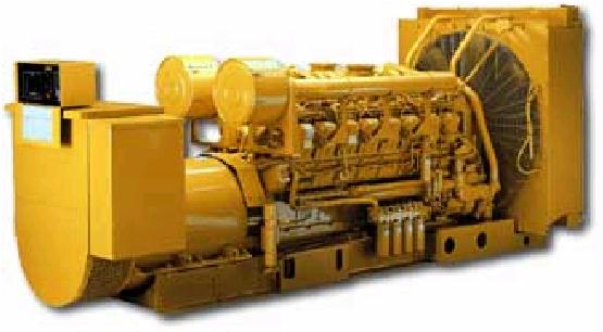
Reciprocating engines, developed more than 100 years ago, were the first of the fossil fuel-driven DG technologies. Both Otto (spark ignition) and Diesel cycle (compression ignition) engines have gained widespread acceptance in almost every sector of the economy and are in applications ranging from fractional horsepower units powering small hand-held tools to 60 MW baseload electric power plants.
Reciprocating engines are machines in which pistons move back and forth in cylinders. Reciprocating engines are a subset of internal combustion engines, which also include rotary engines. Small to medium sized engines are primarily designed for transportation applications and are converted to power generation units with little modification. Larger engines are, in general, designed for power generation, mechanical drive, or marine propulsion. Reciprocating engines are currently available from many manufacturers in all DG size ranges.
Operation
Almost all engines used for power generation are four-stroke and operate in four cycles (intake, compression, combustion, and exhaust). The process begins with fuel and air being mixed. Some engines are turbocharged or supercharged to increase engine output, meaning that the intake air is compressed by a small compressor in the intake system. The fuel/air mixture is introduced into the combustion cylinder, then compressed as the piston moves toward the top of the cylinder.
In diesel units, the air and fuel are introduced separately with fuel injected after the air is compressed by the piston in the engine. As the piston nears the top of its movement, a spark is produced that ignites the mixture (in most diesel engines, the mixture is ignited by the compression alone).
Dual fuel engines use a small amount of diesel pilot fuel in lieu of a spark to initiate combustion of the primarily natural gas fuel. The pressure of the hot, combusted gases drives the piston down the cylinder. Energy in the moving piston is translated to rotational energy by a crankshaft. As the piston reaches the bottom of its stroke the exhaust valve opens and the exhaust is expelled from the cylinder by the rising piston.
Reciprocating engines can be used in three different types of industrial cogeneration applications:
- To produce hot water at around 195° F,
- To produce low temperature steam at around 265° F, and
- To produce heat at higher temperatures, e.g. for drying processes, exhaust gases with temperatures of 930 to 1,000° F can be used directly or by means of a heat exchanger.
Combustion Turbine
History
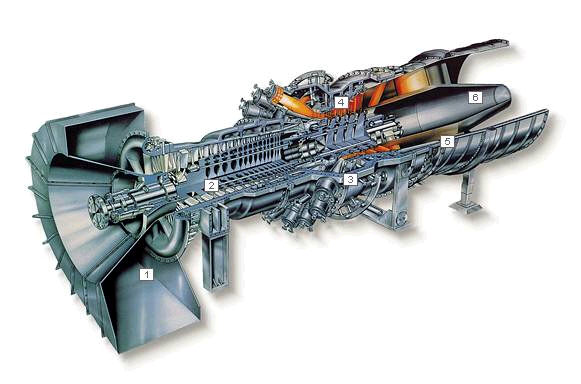
Combustion turbines have been used for power generation for decades and range in size from units starting at about 1 MW to over a 100 MW. Units from 1-15 MW are generally referred to as industrial turbines, a term which differentiates them from larger utility grade turbines and smaller microturbines. Combustion turbines have relatively low installation costs, low emissions, high heat recovery, infrequent maintenance requirements, but low electric efficiency. With these traits, combustion turbines are typically used for cogeneration, as peakers, and in combined cycle configurations.
Operation
Historically, industrial turbines have been developed as aero derivatives using jet propulsion engines as a design base. Some, however, have been designed specifically for stationary power generation or for compression applications in the oil and gas industries. A combustion turbine is a device in which air is compressed and a gaseous or liquid fuel is ignited. The combustion products expand directly through the blades in a turbine to drive an electric generator. The compressor and turbine usually have multiple stages and axial blading. This differentiates them from smaller microturbines that have radial blades and are single staged.
Industrial turbines can be used in two types of industrial cogeneration applications:
- To produce low temperature steam at around 265° F, and
- To produce heat at higher temperatures, e.g. for drying processes, exhaust gases with temperatures of 930 to 1,000° F can be used directly or by means of a heat exchanger.
Some of the principle advantages of the gas turbine are:
- It is capable of producing large amounts of useful power for a relatively small size and weight.
- Since motion of all its major components involve pure rotation (i.e. no reciprocating motion as in a piston engine), its mechanical life is long and the corresponding maintenance cost is relatively low.
- Although the gas turbine must be started by some external means (a small external motor or other source, such as another gas turbine), it can be brought up to full-load (peak output) conditions in minutes as contrasted to a steam turbine plant whose start up time is measured in hours.
- A wide variety of fuels can be utilized. Natural gas is commonly used in land-based gas turbines while light distillate (kerosene-like) oils power aircraft gas turbines. Diesel oil or specially treated residual oils can also be used, as well as combustible gases derived from blast furnaces, refineries and the gasification of solid fuels such as coal, wood chips and bagasse.
- The usual working fluid is atmospheric air. As a basic power supply, the gas turbine requires no coolant (e.g. water).
Steam Turbine
History
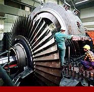
Steam turbines are one of the most versatile and oldest prime mover technologies used to drive a generator or mechanical machinery. Most of the electricity in the United States is generated by conventional steam turbine power plants. The capacity of steam turbines can range from a fractional horsepower to more than 1,300 MW for large utility power plants.
A steam turbine is captive to a separate heat source and does not directly convert a fuel source to electric energy. Steam turbines require a source of high pressure steam that is produced in a boiler or heat recovery steam generator (HRSG).
Steam turbines offer a wide array of designs and complexity to match the desired application and/or performance specifications. In utility applications, maximizing efficiency of the power plant is crucial for economic reasons. Steam turbines for utility service may have several pressure casings and elaborate design features. For industrial applications, steam turbines are generally of single casing design, single or multi-staged and less complicated for reliability and cost reasons.
Operation
The thermodynamic cycle for the steam turbine is the Rankine cycle. The cycle is the basis for conventional power generating stations and consists of a heat source (boiler) that converts water to high pressure steam. The steam flows through the turbine to produce power. The steam exiting the turbine is condensed and returned to the boiler to repeat the process.
A steam turbine consists of a stationary set of blades (called nozzles) and a moving set of adjacent blades (called buckets or rotor blades) installed within a casing. The two sets of blades work together such that the steam turns the shaft of the turbine and the connected load. A steam turbine converts pressure energy into velocity energy as it passes through the blades.
The primary type of turbine used for central power generation is the condensing turbine. Steam exhausts from the turbine at sub-atmospheric pressures, maximizing the heat extracted from the steam to produce useful work.
Steam turbines used for CHP can be classified into two main types:
- Non-condensing or back-pressure turbine
- The extraction or Condensing turbine
Microturbine
History
The technology used in microturbines is derived from aircraft auxiliary power systems, diesel engine turbochargers, and automotive designs. A number of companies are currently field testing demonstration units for small-scale distributed power generation in the 30-400 kW size range. Several units are available commercially, and more are slated to enter the market in 2001 and 2002.
Operation
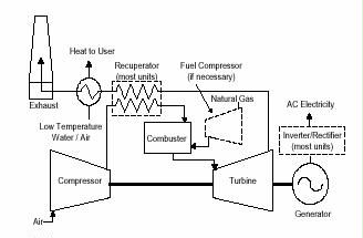
Microturbines consist of a compressor, combustor, turbine, and generator. The compressors and turbines are typically radial-flow designs, and resemble automotive engine turbochargers. Most designs are single-shaft and use a high-speed permanent magnet generator producing variable voltage, variable frequency alternating current (AC) power. An inverter is employed to produce 60 Hz AC power.
Most microturbine units are currently designed for continuous-duty operation and are recuperated to obtain higher electric efficiencies. Non-recuperated engines have lower electric efficiencies, but higher exhaust temperatures, which make them better for some industrial cogeneration applications.
Microturbines can be used in three different types of industrial cogeneration applications:
- To produce hot water at around 195-205° F,
- To produce low temperature steam at around 265° F, and
- To produce heat at higher temperatures, e.g. for drying processes, exhaust gases with temperatures of 930 to 1,000° F can be used directly or by means of a heat exchanger.
Fuel Cell
History
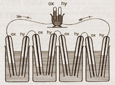
Although the first fuel cell was developed in 1839 by Sir William Grove, the technology was not put to practical use until the 1960’s when NASA installed fuel cells to generate electricity on Gemini and Apollo spacecraft. There are many types of fuel cells currently under development, including phosphoric acid, proton exchange membrane, molten carbonate, solid oxide, alkaline, and direct methanol. However, fuel cells are not generally commercially available, except for a 200 kW phosphoric acid unit made by International Fuel Cells.
Operation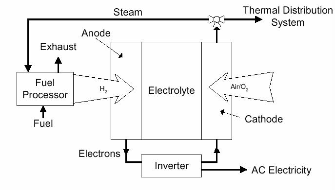
There are many types of fuel cells, but each uses the same basic principle to generate power. A fuel cell consists of two electrodes (an anode and a cathode) separated by an electrolyte. Hydrogen fuel is fed into the anode, while oxygen (or air) enters the fuel cell through the cathode. With the aid of a catalyst, the hydrogen atom splits into a proton (H+) and an electron. The proton passes through the electrolyte to the cathode, and the electrons travel through an external circuit connected as a load, creating a DC current. The electrons continue on to the cathode, where they combine with hydrogen and oxygen, producing water and heat.
The main differences between fuel cell types are in their electrolytic material. Each different electrolyte has both benefits and disadvantages, based on materials and manufacturing costs, operating temperature, achievable efficiency, power to volume (or weight) ratio, and other operational considerations. The part of a fuel cell that contains the electrodes and electrolytic material is called the “stack,” and is a major component of the cost of the total system. Stack replacement is very costly but becomes necessary when efficiency degrades as stack operating hours accumulate.
Fuel cells require hydrogen for operation. However, it is generally impractical to use hydrogen directly as a fuel source; instead, it is extracted from hydrogen-rich sources such as gasoline, propane, or natural gas using a reformer. Cost effective, efficient fuel reformers that can convert various fuels to hydrogen are necessary to allow fuel cells increased flexibility and commercial feasibility.
The fuel cell can be used in two different types of industrial cogeneration applications:
- To produce hot water at around 140° F
- To produce hot water at around 140° F and low temperature steam at 250° F
The unit is very quiet in operation, so it could be used in residential areas. It also has low emissions, so it could be sited in areas where engine drives may not be permitted.
Combined Cycle Power Plants
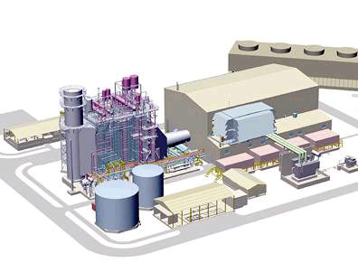
The combined cycle plant is an integration of two types of prime mover the gas turbine and the steam turbine combining many of the advantages of the both. It can provide large amounts of power on short notice with its quick start-up time. It has a short delivery time, a low heat rate, and its capital cost is an effective compromise between pure gas and steam turbines.
For More Information
For a Directory of active vendors and much more info about on-site power production, go to the Energy Solutions Center’s DG Consortium web site at www.poweronsite.org
See the DOE CHP Applications Center web site at www.chpcentermw.org
CHP in the Food & Beverage Manufacturing Industry web site at www.sentech.org/CHP4foodprocessing